Design Loads
The design loads acting on the overall ship structure consist of static and dynamic loads.
 Static loads include dead and live loads, such as hydrostatic loads, and wind loads. Dynamic loads include wave induced hydrodynamic loads, inertia loads due to vessel motion, and impact loads. The various loading conditions and patterns, which are likely to impose the most onerous local and global regimes, are to be investigated to capture the maximum local and global loads in structural analysis. Sloshing and slamming loads should also be taken into account where applicable. When designing ocean-going ships, environmental loads are usually
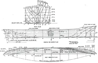
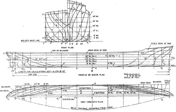
 The distribution of hull girder shear forces and bending moments is calculated by providing the vessel's hull geometry, lightship (i.e. the weight of the steel structure, outfitting and machinery), and deadweight (i.e. cargoes and consumables such as fuel oil, water and stores), as input for each loading condition. An analysis of a cross-sectional member along the length of the ship is required in order to account for the discontinuities in the weight distribution.
The design loads acting on the overall ship structure consist of static and dynamic loads.
 Static loads include dead and live loads, such as hydrostatic loads, and wind loads. Dynamic loads include wave induced hydrodynamic loads, inertia loads due to vessel motion, and impact loads. The various loading conditions and patterns, which are likely to impose the most onerous local and global regimes, are to be investigated to capture the maximum local and global loads in structural analysis. Sloshing and slamming loads should also be taken into account where applicable. When designing ocean-going ships, environmental loads are usually
based on global seastate criteria due to their mobility. While for offshore structures, environmental loads are calculated in accordance with specifically designed routes and/or site data.
Three loading conditions are analyzed, namely, full load condition, ballast load condition, and partial load condition.
StaticLoads
 The distribution of hull girder shear forces and bending moments is calculated by providing the vessel's hull geometry, lightship (i.e. the weight of the steel structure, outfitting and machinery), and deadweight (i.e. cargoes and consumables such as fuel oil, water and stores), as input for each loading condition. An analysis of a cross-sectional member along the length of the ship is required in order to account for the discontinuities in the weight distribution.
Hydrodynamic Coefficients
Each loading condition requires hydrodynamic coefficients to determine the ship's motions and dynamic loads. It is important that a significantly broad range of wave frequencies be considered in this calculation.
Ship motion analysis should be carried out using a suitable method, e.g. linear seakeeping theory and strip theory. Frequency response functions are to be calculated for each load case.
Ship Motion and Short-term /Long-term Response
Short-term response is then obtained by multiplying the frequency response functions by the wave spectra. The long-term response is calculated by using the short-term response and wave statistics, which consist of wave scatter diagrams.
In principle, strength analysis by means of finite element methods should be performed with the following model levels:
Global Analysis
A global analysis models the whole structure with a relatively coarse mesh. For a huge structure like ships, the global model mesh must be quite rough; otherwise too many degrees of fieedom may consume unnecessary man-hours and cause computational difficulty. The overall stiffness and global stresses of primary members of the hull should be reflected in the main features of the structure. Stiffeners may be lumped, as the mesh size is normally greater than the stiffener spacing. It is important to have a good representation of the overall membrane panel stiffness in the longitudinal and transverse directions. This model should be used to study the global response of the structure under the effects of functional and environmental loads, to calculate global stresses due to hull girder bending, and to provide boundary conditions for local FE models. Design loads should reflect extreme sagging and hogging conditions imposed by relevant operation modes such as transit, operating, storm survival, installation, etc.
Local Structural Models
For instance, cargo hold and ballast tank models for ship shaped structures may be analyzed based on the requirements of classification rules.
Certification Classification Authority (CA) acted as an independent body between the vessel's designer, builder, owner, operator and the insurance company. The government's interest of reducing the risks to life and the environment from marine accidents has increased the need for CA's to also provide their expertise in government policies and legislation.
CA's are companies such as:
Bureau Veritas (BV), Det Norske Veritas (DNV), UK Health and Safety Executive (HSE), US Mineral Management Service (MMS), American Bureau of Shipping (ABS), Lloyds Register of Shipping (LR), ClassNK(NK)
Ships and mobile offshore drilling units (MODU) transit from one location to another worldwide and thus the use of the CA's service may avoid the repetitive approvals from the many national governments concerned. The role of the CA has become questioned in recent years concerning the fixed (bottomed supported) structures, which will generally remain at one location within one nation's territorial waters throughout its life.
Codes and standards provide details on how structures should be designed, built, and operated. The difference between a code and a standard is that a code should be followed more rigorously, while a standard sets recommended practices that should be followed. This difference is largely ignored now with, for example, the Eurocode for steel design, which is classified as a national standard.
The range of worldwide codes and Standards is substantial. However, the important aspect of these documents is that they both have national, or in some cases international standing.
Examples of the codes and standards for the design of steel marine structures are the following:
ANSVAWS D1.l, Structural Welding Code, API RP2A (Working Stress Design or Load Resistance Factored Design, Recommended Practice for Planning, Designing and Constructing Fixed Offshore Platforms), IS0 Codes for Design of Offshore Structures, NORSOK Standard N-004, Design of Steel Structures, NS3472, API RP 2A (2001) has been widely applied for design and construction fixed platforms, and serve as a basic document for offshore structural design.
API RF' 2T (1987) has been mainly used for tension leg platforms. It provides comprehensive guidance on design criteria, environmental forces, global design and analysis, structural design.
The design is a complicated and iterative process in which building and solving a FE model is simply the first step. A more important step is that designers use their knowledge and judgment to analyze the results and, if necessary, redesign or reinforce the structure.
First, the engineer must ensure that the results calculated by the FE program are reasonable, and that the model and the load application are correct. This can be achieved by plotting stress contour, the deformation, the reactions & applied load equilibrium, force & moment diagrams, etc. The next step is to check the strength of the structure against relevant design criteria. Load combinations and stress combinations are not always straightforward. Assumptions are usually made to certain degrees both in creating the model and in solving the model. The designers must bear this in mind and be familiar with the FE program being used, in order to account for the assumptions adopted, to evaluate the calculated results, and, if necessary, to modify the results.
In a ship structural design, three load components are considered:
- hull girder load, which consists of the still-waterlwave induced bending moments and shear forces. The hull girder loads are calculated from a number of components. The most significant of these components are the still-water moments and shear forces resulting from the weight of the ship, cargo, and buoyancy. The second major component of hull girder loads is, the dynamic- induced loads that include the vertical and horizontal bending moments, shear forces and torsional moment. These dynamic loads result from wave motions encountered by the ship.
- external pressure, which consists of a static, hydrodynamic, and an impact slamming load. The methods and theories used to determine the external pressure on a ship are usually based on a number of assumptions, such as having a wall-sided hull, small motions of the vessel, and being in an inviscid fluid. Thus, one has to be careful when predicting a value for the external pressure. The external pressure on a vessel is determined by initially dividing the vessel into two parts. The pressures distributed over 40% of the length of the vessel, centered around the amidships are normally very similar from ship to ship. Thus, the calculation of the pressure in these regions is relatively straightforward and is done by applying the results of a complete seakeeping analysis of full form tankers and bulk carriers.
- internal pressure caused by the liquids carried in tanks onboard the ship. This pressure depends on the hydrostatic pressure, the changes in pressure head due to pitching and rolling motions, and the inertial force of the liquid column resulting fkom accelerations of the fluid. The internal pressure in a tank is calculated by a series of formulae specific to the shape of the tank being analyzed. A number of different tank shapes exist, such as J-shaped, rectangular, and U-shaped. Other factors that affect the internal pressure are the amount of liquid carried in the tank, and the location and number of air pipes in the tank.
Yielding Check
The yield check ensures that the stress level on each structural member is below the allowable stress. The allowable stress is defined as the yield limit of the material divided by a safety factor. Stresses calculated fiom different models are combined to derive the equivalent von Mises stress and evaluated against the yield criterion. Component stresses, such as axial stress, bending stress, normal stress in x-direction, normal stress in y-direction, shear stress, etc. as well as combined stresses, are to be evaluated. The combination of global and local stresses should account for actual stress distributions and phases. If the phase information is limited or uncertain, the maximum design value for each component may be combined as the worst scenario. Possible load offset due to the simplified assumptions made in the FE analysis should be accounted for in the stress combinations.
Buckling Check
Structural members subjected to compressive loads may normally buckle before reaching the yield limit. Various buckling modes should therefore be evaluated. Four different modes of buckling are usually recognized:
Mode 1: simple buckling of the plate panel between stiffeners and girders.
Mode 2: flexural buckling of the individual stiffener along with its effective width of plating in a manner analogous to a simple column.
Mode 3: lateral-torsion or tripping mode. The stiffener is relatively weak in torsion, and failure may be initiated by twisting the stiffener in such a way that the joint between stiffener and plate does not move laterally.
Mode 4: overall grillage buckling.
No comments:
Post a Comment